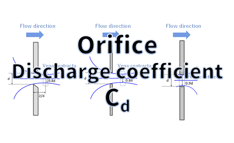
When calculating the flow rate of an orifice, the "Discharge Coefficient ()" is a crucial factor.
Did you know that the value of changes significantly depending on the shape and thickness of the orifice plate?
This article provides a technical explanation of the orifice flow coefficient and its dependence on orifice geometry. Orifice flow calculations are routinely employed in the design of restriction orifices and in flow measurement using orifice plates. In many such calculations the flow coefficient appears as a necessary parameter. This document explains the origin of the flow coefficient and how to allocate its components according to orifice shape for engineering use
You May Also Like
Purpose and Application
Restriction orifices are used to reduce pressure and regulate flow in high‑pressure systems; they are commonly applied as flow control devices or as cost‑effective substitutes for control valves. They are widely used in gas and steam piping. This article focuses on the calculation procedure for the orifice diameter of restriction orifices used in gas and steam piping, and on a simplified method for estimating the orifice flow coefficient for liquid piping.
Theoretical Basis (Bernoulli and Ideal Discharge Velocity)
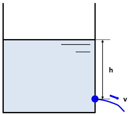
Consider a large open tank (free surface) and an orifice located at a depth h below the free surface. Applying Bernoulli’s principle between the free surface and the orifice yields:
$$P+ρgh=P+\frac{1}{2}ρv^2$$
where P is the pressure at the free surface and at the orifice (atmospheric), ρ is fluid density, g is gravitational acceleration, h is the vertical distance from the free surface to the orifice, and v is the theoretical velocity through the orifice. Rearranging gives the ideal (theoretical) discharge velocity:
$$v=\sqrt{2gh}$$
This theoretical velocity assumes inviscid, lossless flow. In practice, losses due to contraction (vena contracta) and viscous friction reduce the actual velocity. To account for these losses, a discharge correction factor C_d is introduced:
$$v=C_d\sqrt{2gh}$$
The flow coefficient C_d therefore represents the combined effect of contraction losses and velocity (viscous) losses.
Furthermore, The discharge coefficient C_d is commonly decomposed into two multiplicative components:
$$C_d=C_a\times{C_v}$$
C_a — area contraction coefficient (accounts for loss due to contraction/vena contracta).
C_v — velocity coefficient (accounts for viscous and frictional losses).
If C_a and C_v are known, C_d can be computed directly. Typical values for C_v for many orifice configurations are in the range 0.96–0.98; a commonly used engineering value is 0.96.
Sharp‑Edged Orifice (Sharp‑Edged / Thin Plate Orifice)
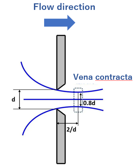
For a sharp‑edged orifice in a thin plate, the flow streamlines contract downstream of the orifice and form a vena contracta. Define:
d: orifice diameter (m)
v: velocity at the orifice plane (m/s)
v': velocity at the vena contracta (m/s)
The contraction coefficient is defined as:
$$C_a=\frac{v}{v'}$$
For a sharp‑edged orifice, the vena contracta diameter is approximately 0.8d. Equating volumetric flow at the orifice plane and at the vena contracta:
$$\frac{π}{4}d^2v=\frac{π}{4}(0.8d)^2v'$$
which simplifies to:
$$v=0.64v'$$
Hence:
$$C_a=\frac{v}{v'}=\frac{0.64v'}{v'}=0.64$$
Using C_v=0.96 (typical), the discharge coefficient becomes:
$$C_d=C_a\times{C_v}=0.64\times0.96=0.61$$
Thus, for a sharp‑edged orifice, a representative value of C_d: 0.61 is obtained and is often used in engineering calculations for thin‑plate orifices in gas piping. For liquid piping where a simplified approach is acceptable, this value may be used as a practical approximation.
Flat Plate Orifice (Thin Plate with Finite Thickness)
The flat plate orifice (also called a short‑length orifice) exhibits contraction behavior that depends on the plate thickness t relative to the orifice diameter d.
t < d/8 (very thin plate):
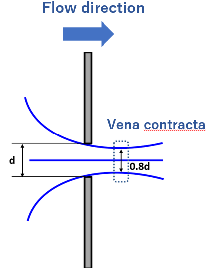
The vena contracta diameter is still approximately 0.8d when the plate is very thin (t< d/8), so the contraction coefficient remains 0.64 and C_d\approx 0.61 (with C_v=0.96). When the plate thickness increases, the contraction region shifts and the vena contracta may form inside the orifice bore. Typical cases:
t<d/8
Ca; 0.64
Cv: 0.96-0.98
Cd: 0.61 (use C_v=0.96 for conservative design)
d/8<t<d (moderate thickness):
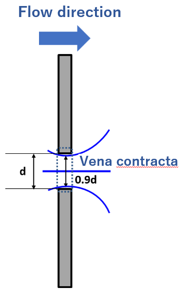
The vena contracta forms inside the orifice bore and its diameter is approximately 0.9d. For this case:
$$C_a=\frac{v}{v'}=\frac{(0.9)^2v'}{v'}=0.81$$
d/8<t<d
Ca; 0.81
Cv: 0.96-0.98
Cd: 0.78-0.79
in practical calculations a rounded representative value of Cd: 0.8 is often used.
d < t (long bore orifice):
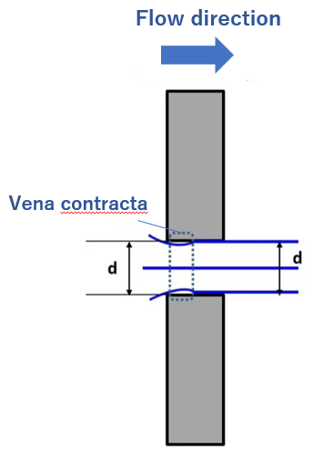
The flow behaves as if the bore and the orifice diameter are equal; contraction is negligible and C_a=1.0. With C_v=0.96-0.98, C_d ranges 0.96–0.98; in practice C_d=0.98 is sometimes used as a representative value for long‑bore orifices.
d<t
Ca; 1.0
Cv: 0.96-0.98
Cd: 0.96-0.98
Trumpet‑Shaped Orifice (Bellmouth / Flared Inlet)
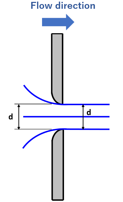
A trumpet‑shaped orifice (bellmouth) is designed to eliminate the vena contracta by providing a smooth converging inlet. For such geometries:
C_a=1.0 (no contraction)
C_v=0.96–0.98
Therefore, the discharge coefficient C_d is typically 0.96–0.98, and Cd=0.98 is commonly adopted in engineering practice for well‑designed bellmouth inlets.
Summary and Engineering Guidance
The discharge coefficient Cd accounts for both contraction losses and viscous/velocity losses and is expressed as Cd=Ca*Cv.
These representative values permit simplified orifice sizing calculations for liquids and gases in plant piping. Note that published tables and standards provide more precise Cd values for specific geometries and Reynolds number ranges; when high accuracy is required, consult experimental data or standards appropriate to the fluid and flow regime.